
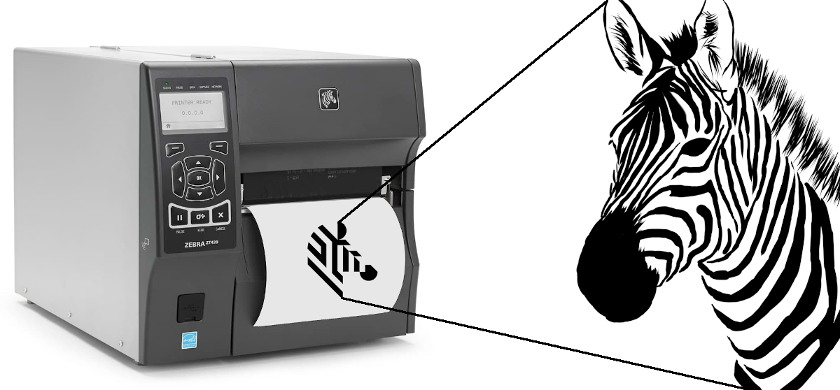
Graphics in Zebra Programming Language
Being a software developer, encountering a programming language you have never even heard of is a rare occasion. However I was recently “fortunate” enough to experience such an encounter. The language in question is Zebra Programming Language (or ZPL for short). This is a page description language developed by Zebra Technologies. It is used primarily for labelling applications. At first ZPL was emulated by many label printers of various producers and later the Zebra Basic Interpreter (ZBI) was integrated into the printer software itself. In this article I will go over the very basics of ZPL, how it handles graphics in a bit more detail and why I had to deal with all of that.
Versions used: Python 3.7.4, Pillow 7.0.0
The task at hand
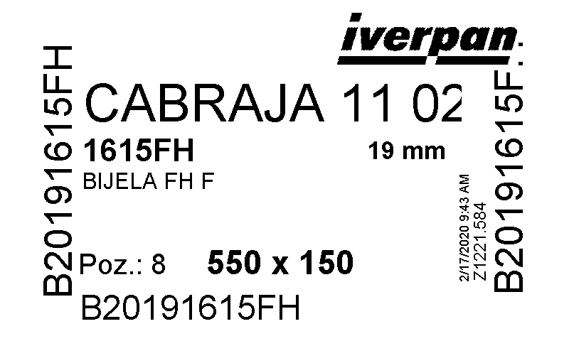
I was tasked with extracting images from ZPL code. Additionally that task was extended with injecting new images into extracted ones. This was a part in development of a system for managing manufacturing facilities by analysing and optimising processes for one of the furniture making companies. They used ZPL printers to print out their work orders. What we wanted to do was extract data on those work orders and show it in a web interface with options to inject additional data into each work order.
To start I was provided with an ZPL code example for one of the work orders which you can see below (truncated version, you can see the whole ZPL here) and around 1600 pages long ZPL manual.
^XA~TA000~JSN^LT0^MNW^MTD^PON^PMN^LH0,0^JMA^PR4,4~SD15^JUS^LRN^CI0^XZ
		~DGR:000.GRF,259840,116,
		,:lK03FHF0,lK03FFE0,:lK07FFC0,lK0IFE0,lK07FFC0,lK0IFC0,:lK0IF80,:lJ01FHF80,lJ01FDF,,::::::lJ0J404H4H0J4H07FFC0H0I4H0704H405FE0I01FF04I404H405FC0,lJ0IFC3FFE00FHF807FHFE0H0IFC7F0FHF9FHF80H0IF8FHFC0FHF8FHF8,lI01FHFC3FFE01FHFH0KF8007FF9FF0FHF3FHFC001FHFCFHFC0FHF3FHFC,lJ0IF83FFE01FHF0
        ### loads more gibberish ### :::::::::::::::::::::::::::::::::::::::::::::::::::::::::::::::::::::::::::::::::::::::::::::::::::::::::::::::::::::::::::::::::::::::::::::::::::::::::::^XA
		^MMT
		^LL2233
		^PW914
		^LS0
		^FT0,2240^XG000.GRF,1,1^FS
		^PQ1,0,1,Y^XZ
		^XA^ID000.GRF^FS^XZ
Getting familiar with ZPL
As there was no way in hell I would read 1600 pages of the manual I started searching for existing solutions. First thing I came across was http://labelary.com/, a great piece of SaaS which offers raw ZPL conversion into PNG images or PDF documents. You can use the online viewer to manually build, tweak and render individual labels, or you can use the web service to ZPL-enable your own software.
Providing their online viewer with my example would result with the following image:
It works. It’s everything I need. The problem is solved.
Right?
Wrong!
The Labelary engine can not be used locally without relying on the public web service which was one of the important requirements this project had to meet.
Not being able to find any meaningful alternative after that I resorted to writing my own ZPL converter. Searching for alternatives and poking around ZPL with Labelary wasn’t for naught since I learned that there are only few relevant ZPL commands i needed to utilise to make the conversion possible. These are discussed in the following chapters.
Graphics in ZPL
The language commands always start with a caret (^) or tilde sign (~). Currently, more than 170 commands exist in ZPL. Each format has to start with the command ^XA and end with ^XZ. Just one other command which defines graphic image in ZPL is of importance and that is the ~DG (Download Graphics) command. The whole image I needed to extract was inside that single command. Now was the time to finally take a peak at that ZPL manual where, on page 158, the ~DG command is thoroughly explained.
The ~DG command downloads an ASCII Hex representation of a graphic image. If .GRF is not the specified file extension, .GRF is automatically appended.
Format: ~DGd:o.x,t,w,data
Parameters:
d- Device to store image
- Values:
R:,E:,B:A: - Default:
R:
o- Image name
- Values: 1 to 8 alphanumeric characters
- If a name is not specified, UNKNOWN is used
x- Extension
- Format:
.GRF
t- Total number of bytes in graphic
w- Number of bytes per row
data- The data string defines the image and is an ASCII hexadecimal representation of the image
- Each character represents a horizontal nibble of four dots
After that there is a simple example which was a perfect starting reference for testing out ZPL conversion during development:
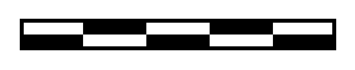
~DGR:SAMPLE.GRF,00080,010,FFFFFFFFFFFFFFFFFFFF8000FFFF0000FFFF00018000FFFF0000FFFF00018000FFFF0000FFFF0001FFFF0000FFFF0000FFFFFFFF0000FFFF0000FFFFFFFF0000FFFF0000FFFFFFFFFFFFFFFFFFFFFFFF^XA^FO20,20^XGR:SAMPLE.GRF,1,1^FS^XZ
This is an example of using the ~DG command to load a checkerboard pattern shown below. The name used to store the graphic is SAMPLE.GRF.
ZPL to image conversion
The steps for converting ZPL to an image seemed pretty straightforward:
- Extract the
~DGcommand from ZPL - Extract the
dataparameter from the~DGcommand - Turn each hexadecimal character from
datato a horizontal nibble of four bits - Draw an image pixel by pixel (bit
1= black pixel, bit0= white pixel)
They were also straightforward to implement and after a bit of work I had the simple example ZPL conversion to an image working flawlessly. The only problem was, when testing it out on the work order example I was given, it did not work. After a closer inspection of the data parameter you can see it starts out like this:
,:lK03FHF0,lK03FFE0,:lK07FFC0,lK0IFE0,lK07FFC0,lK0IFC0,:lK0IF80,:lJ01FHF80,lJ01FDF,,::::::lJ0J404H4H0J4H07FFC0H0I4H0704H405FE0I01FF04I404H405FC0,
Wait a minute… Those aren’t hexadecimal characters.
After digging around a bit more I found out that a custom compression scheme can be used for data in ~DG commands. It is explained in detail on page 1582 of the ZPL manual but here is the summary:
- Uppercase letters from
GtoYand lowercase letters fromgtozrepresent repeat counts on a subsequent hexadecimal valueG: 1, H: 2, I: 3, ..., X: 18, Y: 19, g: 20, h: 40, i: 60, ..., y: 380, z: 400- Several repeat values can be used together to achieve any desired value
- Example 1:
M6represents6666666 - Example 2:
hBrepresentsBBBBBBBBBBBBBBBBBBBBBBBBBBBBBBBBBBBBBBBB - Example 3:
vMBorMvBrepresents 327 hexadecimalB’s
-
A comma (
,) fills the line, to the right, with hexadecimal0’s -
An exclamation mark (
!) fills the line, to the right, with hexadecimalFs - A colon (
:) denotes repetition of the previous line
Following those rules I implemented the data decompression as an extra step after extracting the data parameter from the ~DG command. After that the full ZPL to image conversion was complete and I could finally convert the work order ZPL code example I was given into an appropriate image.
Image to ZPL conversion
Do everything in reverse!
This was rather easy to implement since I already had the ZPL to image conversion. I only had to reverse the steps:
- Convert image to black and white and read it pixel by pixel (black pixel = bit
1, white pixel = bit0) - Turn each horizontal nibble of four bits into a hexadecimal character for
dataparameter - Compress the
data - Generate the
~DGcommand with compresseddata - Generate the ZPL with generated
~DGcommand
Inject an image into ZPL code
Put everything together!
This can now be easily done by combining the conversions:
- Do a ZPL to image conversion
- Use
Pillowto inject desired image into image got from ZPL - Do an image to ZPL conversion
Conclusion
Working with graphics is only a small portion of ZPL capabilities and you can find out all about it in this article. For everything else please consult the manual.